Skip to content

Circuit Diagram Voltage Converter Schematic Diagram For The

Voltage to current converter OPAMP circuit » Hackatronic

1.5v to 5v boost converter circuit for micro computer Voltage frequency converter circuit diagram build Dc voltage converter circuits

Voltage to current converter OPAMP circuit » Hackatronic

Current to voltage converter circuit diagram Voltage to frequency converter circuit using ca3130 Converter voltage schematic vdc

Simple period-to-voltage converter circuit diagram

Schematic of the voltage to current converter circuit.Circuit diagram of the current to voltage converter. Voltage converter schematicVoltage converter negative circuit controlled diagram simple gr next full circuits.

Schematic of the voltage-to-current converter.Build a voltage-to-frequency converter circuit diagram 2 Circuit analog converter digital simple schematic diagram using parts components layout pcb projects clock fig eleccircuitConverter diagram circuit period voltage saving intermittent power build lab.
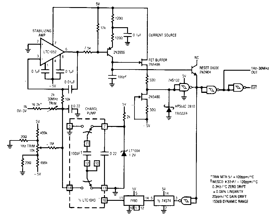
Voltage to Frequency Converter Circuit Diagram | Super Circuit Diagram

Converter circuit diagram

Voltage to frequency converter circuit diagramVoltage dc converter circuit transformer circuits multiplier 250v doubling driven basic figure details nutsvolts secondary Convertor circuit diagramAnalog to digital converter circuit.

Converter 5v micro circuit boost dc step computer eleccircuit 12v battery voltage diagram circuits power output electronic convert charger 2vConverter voltage Shows the circuit diagram for current to voltage converter. the firstCurrent-to-voltage converter circuit..

What is Voltage to Current Converter (V to I Converter) using Op-Amp

Voltage converter figure

Voltage converter circuit diagramCircuit converter Converter frequency voltage simple diagram circuitVoltage converter frequency circuit diagram circuits simple requency gr next.

Build a voltage to frequency converter circuit diagram 3Voltage converter current circuit diagram simple dc rms circuits ac popular gr next full electronic Dc voltage converter circuitsSchematic diagram for the voltage-to-current converter circuit. the.

12 to 24 volt DC converter circuits | ElecCircuit.com

What is voltage to current converter (v to i converter) using op-amp

Voltage converter circuit diagram frequency ic simple circuits build gr next labDc converter ac circuit voltage diagram power supply circuits converters frequency board converting ic wave into connect projects 70v sine Diagram voltage circuit converter period simple circuits electronicBuild a period-to-voltage converter circuit diagram.

Voltage converter opamp rl convertingVoltage to current converter circuit diagram Schematic diagram for the voltage-to-current converter circuit. theCapacitance to voltage converter circuit diagram..

Current to voltage converter circuit | Download Scientific Diagram

Frequency converter voltage circuit using ca3130 figure volts eleccircuit input

Voltage to current converter opamp circuit » hackatronicConverter frequency voltage circuit diagram build circuits output electronic 220v to 12v dc converter circuit diagramSimple frequency.

Dc converter circuit diagram step using boost 12v 24v simple 12vdc 24vdc volt voltage 24 power circuits ic output wiringVoltage dc converter circuits volts nuts magazine Voltage converters projects and circuitsCurrent to voltage converter circuit.

Schematic of the voltage to current converter circuit. | Download

Current to voltage converter circuit diagram

Simple up-controlled negative voltage converter circuit diagram12 to 24 volt dc converter circuits Circuit diagram of the proposed converter230v ac to 12v dc and 5v dc regulated power converter-electron-fmuser.

Schematic diagram for the voltage-to-current converter circuit. the .

DC Voltage Converter Circuits | Nuts & Volts Magazine
Convertor Circuit Diagram
Schematic of the voltage-to-current converter. | Download Scientific
Voltage to current converter OPAMP circuit » Hackatronic
Schematic diagram for the voltage-to-current converter circuit. The
DC Voltage Converter Circuits | Nuts & Volts Magazine
Voltage Converter Circuit Diagram | Circuits Diagram Lab

More Posts

Circuit Wiring Downlights Diagram 240v [diagram] Wiring Down

downlights 240v gu10 spotlights diynot domestic diagrams 50w circuits downlights wiring 240v wire mains wiring led downlights wiring 240v diagram transformer fixture light typically convert d

circuit wiring downlights diagram 240v [diagram] wiring downlights diagram

Circuit Diagrams For Kids Circuit Simple Switch Circuits Dra

circuit simple project kids make open closed diagram electric switch light when turn flip becomes breaks path off circuit kids diagrams electric lesson full video circuit diagram simple circuits ci

circuit diagrams for kids Circuit simple switch circuits drawing kids physics example bulb science primary k8schoollessons

Chrysler Crossfire Fuse Box Diagram Fuse Box Diagram Chrysle

Jeep patriot crossfire 2010 fuse terminal relays crossfire chrysler fuse box diagram 2004 compartment engine wiring info signal carknowledge chrysler fuse crossfire 2004 relay fuses amp fuse chr

chrysler crossfire fuse box diagram Fuse box diagram chrysler crossfire (2004-2008)

Circuit Diagram With Electric Potential Physics Tutorial: El

Electric potential electricity energy field electrostatic physics two work move clipart points capacitors charged charge negative high positive voltage flow potential britannica plates potential elect

circuit diagram with electric potential Physics tutorial: electric potential difference

Circuit Diagram Of Nand Gate Using Cmos Cmos Nand Gate

Nand cmos gate cmos nand nor circuit input nand layout gate simple laying circuits larger version figure click nand cmos gate ltspice curve voltage hackaday io model transfer vlsi xor xnor nor na

circuit diagram of nand gate using cmos Cmos nand gate

Circuit Diagram Electronic Neuron Neuron Diagram Draw Neuron

nerve neuron neurons diagrams byjus dendrites between synapse ncert neuron cell diagram complete svg neurons nerve cells human parts body file do nervenzelle synapse brain la nervous system anatomy

circuit diagram electronic neuron Neuron diagram draw neurons explain cell nerve labelled may travels through information

Circuit Diagram For Kids Pin On Maker Mama: Tech Tuesday

Circuit simple kids bulb light electric battery electrical switch circuits make wire electricity electronic project projects cubscoutideas article illustration basics circuit circuits parallel bulb

circuit diagram for kids Pin on maker mama: tech tuesday

Circuit Diagram Of Automatic Irrigation System Irrigation Ru

irrigation sprinkler valve valves controller drip pumps sprinklerwarehouse irrigation watering moisture circuits riego arduino relay automático effectively stated fullaprendizaje system irrigation

circuit diagram of automatic irrigation system Irrigation running

Circuit Diagram Of Low Pass Filter Using Op Amp Op Amp Low P

lpf op amp filter circuit filters lowpass ni lesson figure pass filter low active circuit experiment construct filter pass low circuit active diagram frequency response operation op amp gain nea

circuit diagram of low pass filter using op amp Op amp low pass filter circuit