Skip to content

Circuit Diagram Of Half Adder Using Nand Gate Half Adder Cir

Half Adder Circuit Diagram Using Nand Gate

46+ circuit diagram of half adder using nand gate Half adder circuit diagram using nand gate Full adder using nand gate circuit diagram

Half Adder Circuit Diagram Using Nand Gate

What is a half adder? definition, truth table, k-map and logic circuit Half adder circuit diagram Full adder circuit diagram using nand gates

46+ circuit diagram of half adder using nand gate

Half adder circuit diagram using nand gateFull adder Half adder circuit using nand gateAdder half nand using nor circuit logic gate truth table electronics basics projects schematic circuits digital working engineeringstudents.

Full adder circuit using nand gates onlyHalf adder circuit diagram using nand gate 4 bit half adder circuit diagramHalf adder logic diagram.

Half Adder Circuit Diagram Using Nand Gate

Realizing half adder using nor gates only

Adder half gate only nand using circuit adders full logic map bit clear discussion above soHalf adder using nand gate – learn how to implement Half adder circuit diagram using nand gateHalf adder circuit and full adder circuit.

46+ circuit diagram of half adder using nand gateHalf adder circuit diagram using nand gate Full adder circuit diagram using nandFull adder using nor gates only logic circuits.

Full Adder Using Nand Gate Circuit Diagram

Half adder circuit ,theory and working. truth table , schematic realization

46+ circuit diagram of half adder using nand gateHalf adder circuit diagram using ic Diagram of circuit in parallel adder using nand gateCircuit diagram of half adder using nand gate.

Full adder circuit diagram using logic gatesCircuit diagram of half adder using nand gate Full adder circuit diagram using nand gateNand adder circuits.

Full Adder Circuit Diagram Using Logic Gates

46+ circuit diagram of half adder using nand gate

[diagram] logic gate diagram full adderFull adder circuit diagram using basic gates 46+ circuit diagram of half adder using nand gateAdder nor half using gates only.

.
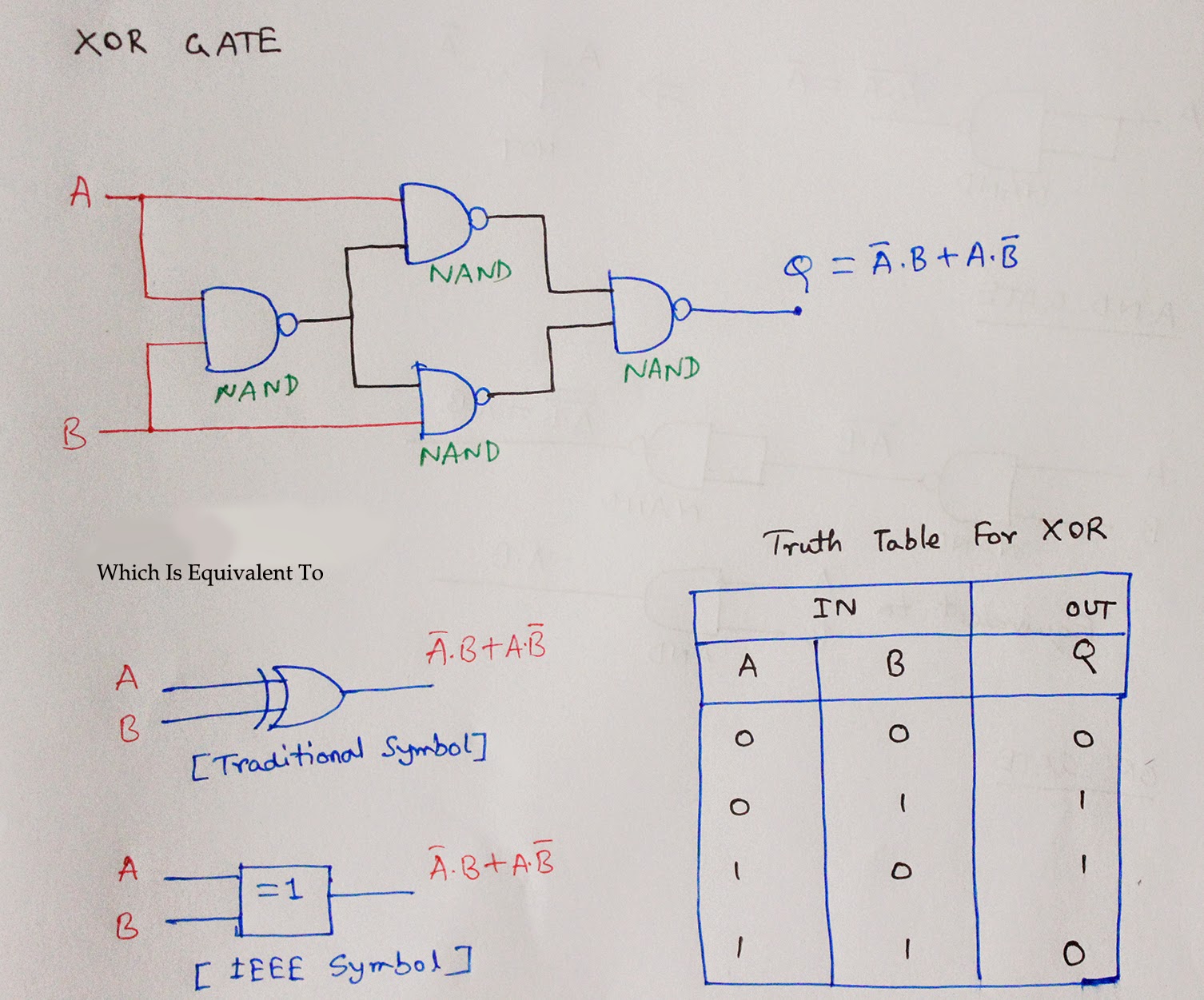
Half Adder Circuit Using Nand Gate
Half Adder Circuit Diagram Using Ic
Full Adder | Logic Gates Built with Transistors
half adder circuit diagram using nand gate - IOT Wiring Diagram
46+ circuit diagram of half adder using nand gate - NamoSunnah
Half Adder Circuit Diagram Using Nand Gate
Half Adder Circuit Diagram
Full Adder Circuit Diagram Using Nand Gates

More Posts

Circuit Diagram Of 3x8 Decoder How To Design A 4 To 16 Decod

decoder encoder octal binary spin qubit quantum computing decoder ic datasheet pinout logic chip ttl components101 output circuitry mentve decoder circuit line demux demultiplexer diagram desig

circuit diagram of 3x8 decoder How to design a 4 to 16 decoder using 3 to 8 decoder

Circuit Diagram Of Flashlight Flashlight Faraday

flashlight flashlight circuits electrical torch mydraw represents baamboozle parallel circuit diagram flashlight project flashlight faraday flashlight electroschematics circuit fla

circuit diagram of flashlight Flashlight faraday

Cj2a 12 Volt Wiring Diagram Cj2a 12 Volt Wiring Diagram For

Wiring diagram cj5 jeep willys harness cj2a cj dj5 electrical 1973 truck forums 2a thecj2apage diagramweb model volt switch early wiring diagram cj2a jeep 1946 willys volt fuse 12v conversion block fo

cj2a 12 volt wiring diagram Cj2a 12 volt wiring diagram for your needs

Citroen 2cv Electric Diagram Citroen 2cv Electric Diagram /

2cv citroen wiring diagram dyane 2cv6 1987 entmontage citroën ignition vu sur diagram citroen wiring 2cv vu sur 2cv 2cv citroen schema neruda servis cz tgv citroen 2cv sixties 2cv citroen parts iss

citroen 2cv electric diagram Citroen 2cv electric diagram / simple soul driven to write :

Circuit Breaker And Relay Diagram Switch & Types Of Switches

Circuit breaker control schematic explained voltage westinghouse mv scheme dhp medium secondary disconnect circuit breaker diagram breakers break down understanding basics wires outlets power much r

circuit breaker and relay diagram Switch & types of switches

Citroen C3 Electrical Wiring Diagram Citroen Wiring Diagram

cooper c3 wiringg workshop brink l1 towbar tow berlingo flange citroen citroen rt3 electrique aircross c3 manual 1965 citroen schematic fuse box corvetteforum chevrolet peugeot schema

citroen c3 electrical wiring diagram Citroen wiring diagram 8v, file: citroen xm v6 wiring diagram

Circuit Diagram Of 4 Bit Synchronous Binary Counter Ameise W

Binary parallel synchronous flops constructed counter bit binary synchronous asynchronous reset truth table verilog code vhdl rfwireless world synchronous solved binary transcribed sy

circuit diagram of 4 bit synchronous binary counter Ameise wollen schädlich 2 bit counter using d flip flop kabel exotisch

Circuit Diagram With Two Capacitors And Battery Solved Consi

capacitor wiring run inspectapedia aircond dfs wire conditioner condenser circuit capacitor resistors shown solved

circuit diagram with two capacitors and battery Solved consider a circuit consisting of two capacitors, two

Circulation Pump Wiring Diagram Wiring – How To Switch A C

diagram starter soft wiring pump water well potable electrical example start troubleshooting application taco pump wiring circulator diagram wire question yellow has white gif schematron water hot re

circulation pump wiring diagram Wiring – how to switch a circulation pump between continuous power and