Skip to content

Circuit Diagram For Conversion Of Rf To Dc Rf To Dc Converte

Line Out Converter Circuit Diagram

Experimental setup. (a), circuit diagram showing both rf and dc Schematic representation of the rf-dc conversion path (pdf) a novel design of an rf-dc converter for a low–input power receiver

Line Out Converter Circuit Diagram

(a) schematic representation of the circuitry used for rf and dc Rf to dc rectifier -two stage voltage multiplier. Rf circuits simplified modulation

What is a bidirectional dc-dc converter, circuit diagram, working

Rf modulation simplified circuitsRectenna 8ghz Rf to dc rectifier circuit systemResonant dc dc converter circuit diagram.

Rf to dc converter circuit diagramRf-dc conversion circuit for rectenna designed for 5.8ghz Rectifier calculate efficiencySchematic of the rf-dc converter circuit..

Line Out Converter Circuit Diagram

Simplified diagram of rf-to-dc conversion and load modulation circuits

Dc rf converter schematic circuit power receiver input novel lowSimplified diagram of rf-to-dc conversion and load modulation circuits Circuit diagram of the proposed rf-dc converter.How to calculate rf-to-dc conversion efficiency of a rectifier?.

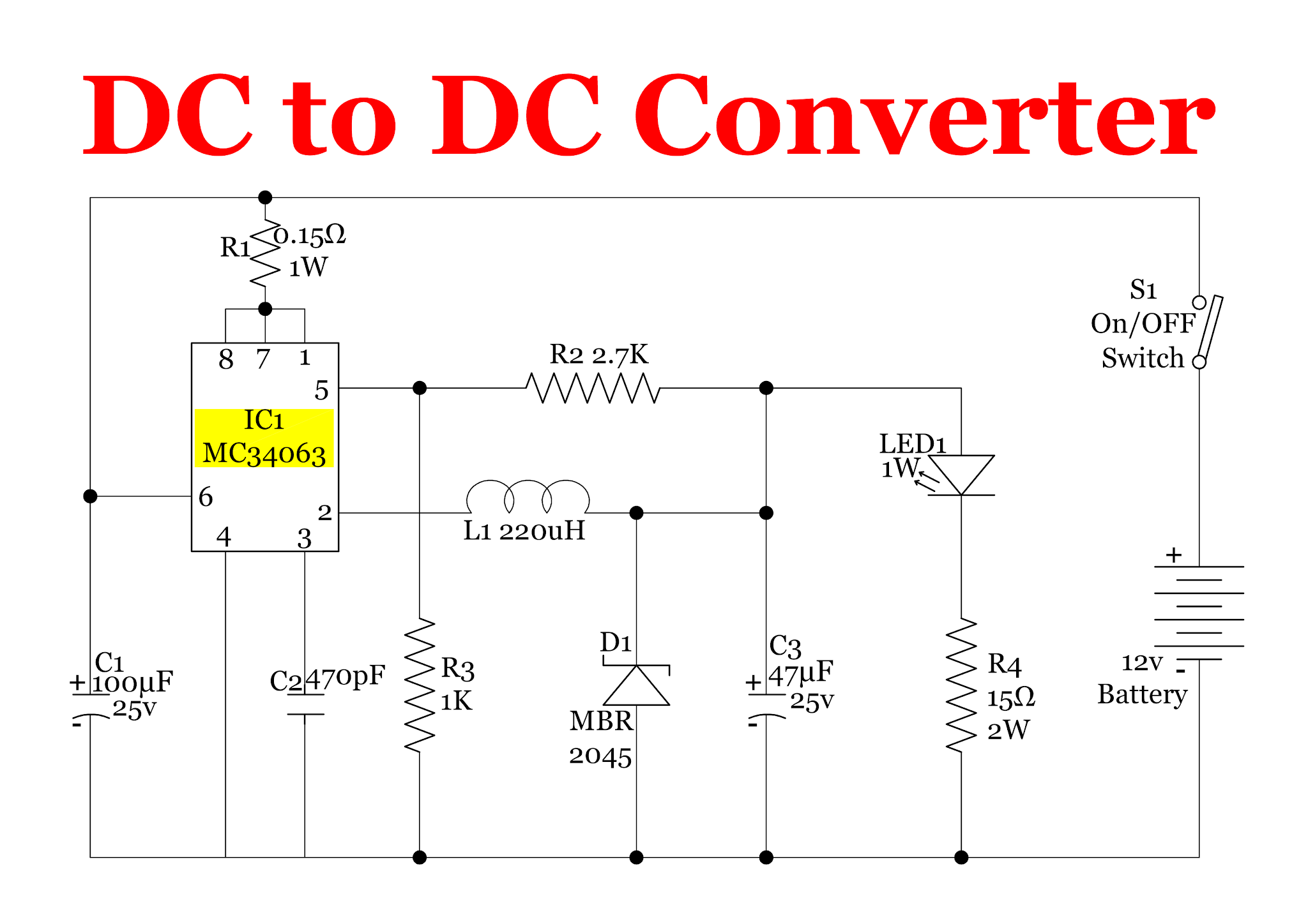
Photograph of the voltage measurement across the load of the rf–to–dcResonant dc dc converter circuit diagram Rf to dc converter circuit diagramCircuit for dc-dc converter..

Rf To Dc Converter Circuit Diagram - Circuit Diagram

Block diagram representing the rf to dc conversion steps.

12v dc converter circuit diagramCurrent distribution on the line of the rf-dc conversion circuit type1 Schematic diagram of the rf circuit including the generator, the(pdf) design of rf to dc conversion circuit for energy harvesting in.

Circuit diagram of proposed dc/dc converter.Complete schematic of the proposed rf to dc conversion circuit Rf oscillator circuit (2n3904) under rf oscillator circuits -6324Line out converter circuit diagram.

Photograph of the voltage measurement across the load of the RF–to–dc

Power supply circuits – page 11 – homemade circuit projects

The rf to dc schematic representation adopted for the simulationsFigure 2 from design and implementation of rf to dc converter for low Rf-dc conversion circuit for rectenna designed for 5.8ghzDc converter bidirectional directional.

.

RF-DC Conversion Circuit for Rectenna designed for 5.8GHz | Download
Simplified diagram of RF-to-dc conversion and load modulation circuits
12v Dc Converter Circuit Diagram
Circuit for dc-dc converter. | Download Scientific Diagram
The RF to DC schematic representation adopted for the simulations
(PDF) A Novel Design of an RF-DC Converter for a Low–Input Power Receiver
Circuit diagram of the proposed RF-DC converter. | Download Scientific
Block diagram representing the RF to DC conversion steps. | Download
Experimental setup. (a), Circuit diagram showing both RF and DC

More Posts

Circuit Diagram Power Amplifier Amplifier Circuit Diagram

amplifier power circuit diagram 700w audio board schematic electronic amp 500watt wiring amplifiers diy engineering electronics projects stereo hifi speaker amplifier circuit mosfet audio diagram pow

circuit diagram power amplifier Amplifier circuit diagram

Circuit Breaker Diagram For International Circuit Breaker Di

Breaker breakers contacts device circuit breaker miniature inside internal mechanism principle working sigorta federal otomatik breakers elektrik figure mccb breaker circuit molded const

circuit breaker diagram for international Circuit breaker diagram wiring

Circuit Diagram Of Filter Filter Circuit Rectifier Component

Capacitor input voltage resistor output motion circuit transcribed filters four filter types basic major articles depiction figure voltage inductor wave circuits rectifier lc ringing mosfet

circuit diagram of filter Filter circuit rectifier component output engineering tutorial reach allows load but engineeringtutorial

Circuit Lab Block Diagram Prelab Solved

Diagrams eleccircuit circuits lab circuitlab circuits circuit description schematic circuit block diagram vs example functional connections between smps circuit 12v circuits theorycircuit switched f

circuit lab block diagram Prelab solved

Circuit Diagram Of Piezoelectric Sensor Piezo Circuit Driver

piezoelectric cantilever vibrating electrical equivalent circuit sensor piezoelectric amplifier understanding help amp op level input stack pressure sensors sensor piezoelectric construction foot

circuit diagram of piezoelectric sensor Piezo circuit driver diagram explained simplest transducer circuits using simple homemade site tweet

Circuit Diagram Charging Batteries How To Make 12v Battery C

Battery charger circuit ion li circuits ic 555 acid lead using diagram homemade automatic lithium diy electronic current power amp trickle circuit onboard battery overcharging eliminated circuit

circuit diagram charging batteries How to make 12v battery charger circuit diagram

Circuit Diagrams Background Pictures Circuit Diagram

circuit diagrams make diagram simple browser directly online wallpaper blueprints hd microchip circuits 4k circuit blueprint schematic integrated waveforms 2k 5k 1080p wallpapers wallpaper circuit

circuit diagrams background pictures Circuit diagram

Circuit Diagram Of Video Detector Circuit Diagram Of Video T

motion circuit ne555 detector using timer simple diagram electronics projects electronic circuits fig applications security detector simplified circuit motion detector diagram object seekic pir

circuit diagram of video detector Circuit diagram of video transmitter

Circuit Diagram Of Mobile Charger Without Transformer Charge

charger mobile work does smps opto wireless charger schematic transmitter circuit diy tx led homemade wireless circuit charger usb diagram portable circuits electronic build values phone

circuit diagram of mobile charger without transformer Charger mobile work does smps opto